
The electric current through the copper wire has produced a magnetic effect. Thus we can say that electricity and magnetism are linked to each other. Then, what about the reverse possibility of an electric effect of moving magnets?
A compass needle gets deflected when brought near a bar magnet. A compass needle is, in fact, a small bar magnet. The ends of the compass needle point approximately towards north and south directions. The end pointing towards north is called north seeking or north pole. The other end that points towards south is called south seeking or south pole.
When the region surrounding a magnet, in which the force of the magnet can be detected, is said to have a Magnetic Field. The lines along which the iron filings align themselves represent magnetic field lines.
Magnetic field is a quantity that has both direction and magnitude. The direction of the magnetic field is taken to be the direction in which a north pole of the compass needle moves inside it. Therefore it is taken by convention that the field lines emerge from North Pole and merge at the south pole.
The relative strength of the magnetic field is shown by the degree of closeness of the field lines. The field is stronger, that is, the force acting on the pole of another magnet placed is greater where the field lines are crowded.
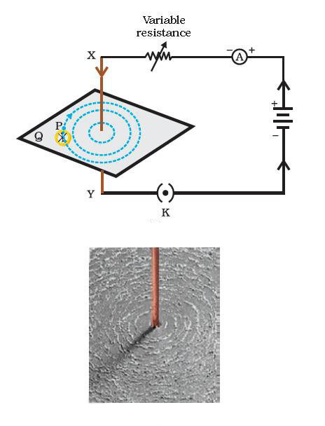
We have learnt that an electric current through a metallic conductor produces a magnetic field around it.
If the current is increased, the deflection also increases. It indicates that the magnitude of the magnetic field produced at a given point increases as the current through the wire increases. The magnetic field produced by a given current in the conductor decreases as the distance from it increases. It can be noticed that the concentric circles representing the magnetic field around a current carrying straight wire become larger and larger as we move away from it.
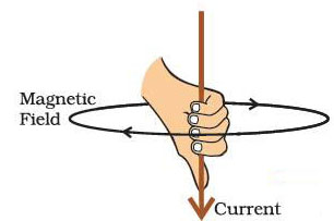
A convenient way of finding the direction of magnetic field associated with a current carrying conductor.
As we know that the magnetic field produced by a current-carrying straight wire depends inversely on the distance from it. Similarly at every point of a current-carrying circular loop, the concentric circles representing the magnetic field around it would become larger and larger as we move away from the wire.
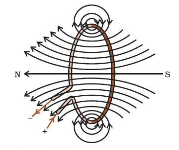
By the time we reach at the centre of the circular loop, the arcs of these big circles would appear as straight lines. Every point on the wire carrying current would give rise to the magnetic field appearing as straight lines at the center of the loop. By applying the right hand rule, it is easy to check that every section of the wire contributes to the magnetic field lines in the same direction within the loop.
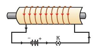
While a coil of many circular turns of insulated copper wire wrapped closely in the shape of a cylinder is called a solenoid. The pattern of the magnetic field lines around a current carrying solenoid.
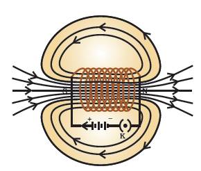
The field lines inside the solenoid are in the form of parallel straight lines. This indicates that the magnetic field is the same at all points inside the solenoid. That is, the field is uniform inside the solenoid.
A strong magnetic field produced inside a solenoid can be used to magnetise a piece of magnetic material, like soft iron, when placed inside the coil. The magnet so formed is called an electromagnet.
We learnt that an electric current flowing through a conductor produces a magnetic field. The field so produced exerts a force on a magnet placed in the vicinity of the conductor. French scientist Andre Marie Ampere (1775–1836) suggested that the magnet must also exert an equal and opposite force on the current carrying conductor.
The force due to a magnetic field acting on a current-carrying conductor. There are various devices that use current-carrying conductors and magnetic fields include electric motor, electric generator, loudspeakers, microphones and measuring instruments.
An electric motor is a rotating device that converts electrical energy to mechanical energy. Electric motor is used as an important component in electric fans, refrigerators, mixers, washing machines, computers, MP3 players etc.
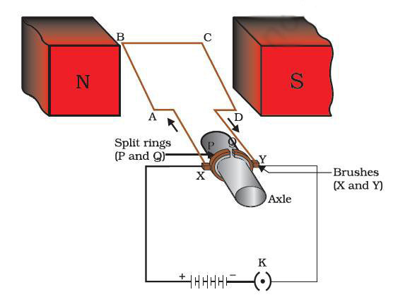
An electric motor consists of a rectangular coil ABCD of insulated copper wire. The coil is placed between the two poles of a magnetic field such that the arm AB and CD are perpendicular to the direction of the magnetic field. The ends of the coil are connected to the two halves P and Q of a split ring. The inner sides of these halves are insulated and attached to an axle.
Current in the coil ABCD enters from the source battery through conducting brush X and flows back to the battery through brush Y. Notice that the current in arm AB of the coil flows from A to B. In arm CD it flows from C to D, that is, opposite to the direction of current through arm AB. On applying Fleming's left hand rule for the direction of force on a current carrying conductor in a magnetic field.
Therefore the coil and the axle rotate half a turn more in the same direction. The reversing of the current is repeated at each half rotation, giving rise to a continuous rotation of the coil and to the axle.
The commercial motors use –
(i)An electromagnet in place of permanent magnet;
(ii)Large number of turns of the conducting wire in the current-carrying coil; and
(iii)A soft iron core on which the coil is wound.
The soft iron core, on which the coil is wound, plus the coils, is called an armature. This enhances the power of the motor.
We learn that when a current-carrying conductor is placed in a magnetic field such that the direction of current is perpendicular to the magnetic field, it experiences a force. This force causes the conductor to move. Now let us imagine a situation in which a conductor is moving inside a magnetic field or a magnetic field is changing around a fixed conductor.
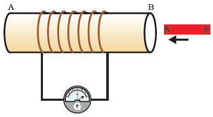
When the coil and the magnet are both stationary, there is no deflection in the galvanometer. It is, thus, clear from this activity that motion of a magnet with respect to the coil produces an induced potential difference, which sets up an induced electric current in the circuit. Which a changing magnetic field in a conductor induces a current in another conductor, is called electromagnetic induction.
The induced current is found to be the highest when the direction of motion of the coil is at right angles to the magnetic field. In this situation, we can use a simple rule to know the direction of the induced current.
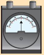
A galvanometer is an instrument that can detect the presence of a current in a circuit. The pointer remains at zero (the centre of the scale) for zero current flowing through it. It can deflect either to the left or to the right of the zero mark depending on the direction of current.
Based on the phenomenon of electromagnetic induction, This principle is also employed to produce large currents for use in homes and industry. In an electric generator, mechanical energy is used to rotate a conductor in a magnetic field to produce electricity.
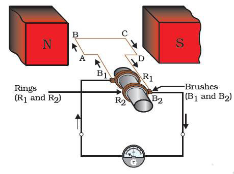
The difference between the direct and alternating currents is that the direct current always flows in one direction, whereas the alternating current reverses its direction periodically. Most power stations constructed these days produce AC. In India, the AC changes direction after every 1/100 second, that is, the frequency of AC is 50 Hz. An important advantage of AC over DC is that electric power can be transmitted over long distances without much loss of energy.
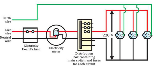
We receive supply of electric power through a main supply (also called mains), either supported through overhead electric poles or by underground cables. One of the wires in this supply, usually with red insulation cover, is called live wire (or positive). Another wire, with black insulation, is called neutral wire (or negative). In our country, the potential difference between the two is 220 V.
At the meter-board in the house, these wires pass into electricity meter through a main fuse. Through the main switch they are connected to the line wires in the house. These wires supply electricity to separate circuits within the house. Often, two separate circuits are used, one of 15 A current rating for appliances with higher power ratings such as geysers, air coolers, etc. The other circuit is of 5 A current rating for bulbs, fans, etc. The earth wire, which has insulation of green colour, is usually connected to a metal plate deep in the earth near the house.
Each appliance has a separate switch to ‘ON’/‘OFF’ the flow of current through it. In order that each appliance has equal potential difference, they are connected parallel to each other. the current in the circuit abruptly increases. This is called short-circuiting. The use of an electric fuse prevents the electric circuit and the appliance from a possible damage by stopping the flow of unduly high electric current. The Joule heating that takes place in the fuse melts it to break the electric circuit.
Overloading can also occur due to an accidental hike in the supply voltage. Sometimes overloading is caused by connecting too many appliances to a single socket.