
Electricity has an important place in modern society. It is a controllable and convenient form of energy for a variety of uses in homes, schools, hospitals, industries and so on.
The torch gives light only when its switch is on. A switch makes a conducting link between the cell and the bulb. A continuous and closed path of an electric current is called an electric circuit. Now, if the circuit is broken anywhere (or the switch of the torch is turned off), the current stops flowing and the bulb does not glow.
Electric current is expressed by the amount of charge flowing through a particular area in unit time. In other words, it is the rate of flow of electric charges. In circuits using metallic wires, electrons constitute the flow of charges. However, electrons were not known at the time when the phenomenon of electricity was first observed. So, electric current was considered to be the flow of positive charges and the direction of flow of positive charges was taken to be the direction of electric current. Conventionally, in an electric circuit the direction of electric current is taken as opposite to the direction of the flow of electrons, which are negative charges.
Flow of charges in a conducting metallic wire, the gravity, of course, has no role to play; the electrons move only if there is a difference of electric pressure – called the potential difference – along the conductor. This difference of potential may be produced by a battery, consisting of one or more electric cells. The chemical action within a cell generates the potential difference across the terminals of the cell, even when no current is drawn from it. When the cell is connected to a conducting circuit element, the potential difference sets the charges in motion in the conductor and produces an electric current. In order to maintain the current in a given electric circuit, the cell has to expend its chemical energy stored in it.
Potential difference (V) between two points = Work done (W)/Charge (Q)
V = W/Q
The SI unit of electric potential difference is volt (V), named after Alessandro Volta (1745 – 1827), an Italian physicist. One volt is the potential difference between two points in a current carrying conductor when 1 joule of work is done to move a charge of 1 coulomb from one point to the other.
Therfore, 1 Volt = 1 Joule/1 Coulomb
The potential difference is measured by means of an instrument called the voltmeter. The voltmeter is always connected in parallel across the points between which the potential difference is to be measured.
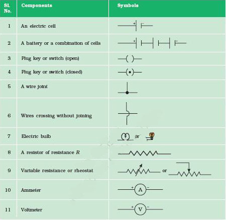
Draw a schematic diagram, in which different components of the circuit are represented by the symbols conveniently used. Conventional symbols used to represent some of the most commonly used electrical components.
In 1827, a German physicist Georg Simon Ohm (1787–1854) found out the relationship between the current I, flowing in a metallic wire and the potential difference across its terminals. The potential difference, V, across the ends of a given metallic wire in an electric circuit is directly proportional to the current flowing through it, provided its temperature remains the same. This is called Ohm's law. In other words –
V ∝ I
or V/I = Constant
= R
or V = IR
R is a constant for the given metallic wire at a given temperature and is called its resistance. It is the property of a conductor to resist the flow of charges through it. Its SI unit is ohm, represented by the Greek letter Ω. According to Ohm's law,
R = V/I
When the ammeter reading decreases to one-half when the length of the wire is doubled. The ammeter reading is increased when a thicker wire of the same material and of the same length is used in the circuit. A change in ammeter reading is observed when a wire of different material of the same length and the same area of cross-section is used. The resistance of the conductor depends –
Precise measurements have shown that resistance of a uniform metallic conductor is directly proportional to its length (l) and inversely proportional to the area of cross-section (A). That is,
R ∝ l
R ∝ 1/A
R ∝ l/A
R = ρ 1/A
Where ρ (rho) is a constant of proportionality and is called the electrical resistivity of the material of the conductor. The SI unit of resistivity is Ω m. It is a characteristic property of the material. The metals and alloys have very low resistivity in the range of 10-8 Ω m to 10-6 Ω m. They are good conductors of electricity. Insulators like rubber and glass have resistivity of the order of 1012 to 1017 Ω m. Both the resistance and resistivity of a material vary with temperature.
Electrical resistivity*of some substances at 20°C
|
Material |
Resistivity (Ω m) |
|
|
Conductors |
Silver |
1.60 x 10⁻⁸ |
|
Copper |
1.62 x 10⁻⁸ |
|
|
Aluminum |
2.63 x 10⁻⁸ |
|
|
Tungsten |
5.20 x 10⁻⁸ |
|
|
Nickel |
6.84 x 10⁻⁸ |
|
|
10.0 x 10⁻⁸ |
||
|
Chromium |
12.9 x 10⁻⁸ |
|
|
Mercury |
94.0 x 10⁻⁸ |
|
|
Manganese |
1.84 x 10⁻⁶ |
|
|
Alloys |
Constantan (alloy of Cu and Ni) |
49 x 10-6 |
|
Manganin (alloy of Cu, Mn and Ni) |
44 x 10-6 |
|
|
Nichrome (alloy of Ni, Cr, Mn and Fe) |
100 x 10-6 |
|
|
Insulators |
Glass |
1010 – 1014 |
|
Hard rubber |
1013 – 1016 |
|
|
Ebonite |
1015 – 1017 |
|
|
Diamond |
1012 – 1013 |
|
|
Paper (dry) |
1012 |
Use these values for solving numerical problems.
There various electrical gadgets, we often use resistors in various combinations. Here we Here we n various electrical gadgets, we often use resistors in various combinations.
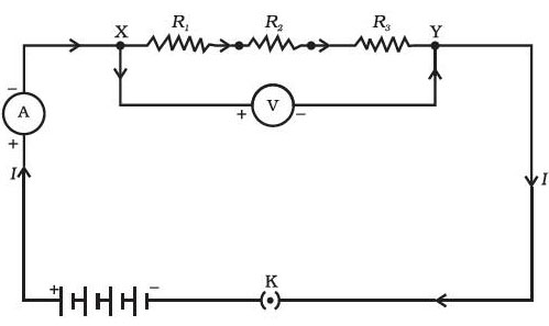
n various electrical gadgets, we often use resistors in various combinations. an electric circuit in which three resistors having resistances R1, R2 and R3, respectively, are joined end to end. Here the resistors are said to be connected in series.
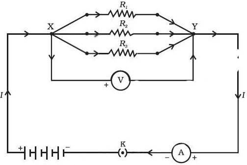
A combination of resistors in which three resistors are connected together between points X and Y. Here, the resistors are said to be connected in parallel.
The value of the current in the ammeter is the same, independent of its position in the electric circuit. It means that in a series combination of resistors the current is the same in every part of the circuit or the same current through each resistor.
A parallel circuit divides the current through the electrical gadgets. The total resistance in a parallel circuit is decreased. Particularly when each gadget has different resistance and requires different current to operate properly.
We know that a battery or a cell is a source of electrical energy. The chemical reaction within the cell generates the potential difference between its two terminals that sets the electrons in motion to flow the current through a resistor or a system of resistors connected to the battery. the source energy in maintaining the current may be consumed into useful work (like in rotating the blades of an electric fan). Rest of the source energy may be expended in heat to raise the temperature of gadget.
If the electric circuit is purely resistive, that is, a configuration of resistors only connected to a battery; the source energy continually gets dissipated entirely in the form of heat. This is known as the heating effect of electric current. This effect is utilised in devices such as electric heater, electric iron etc.
It is undesirable as it converts useful electrical energy into heat. In electric circuits, the unavoidable heating can increase the temperature of the components and alter their properties. However, heating effect of electric current has many useful applications. The electric laundry iron, electric toaster, electric oven, electric kettle and electric heater are some of the familiar devices based on Joule's heating.
When an electric energy is dissipated or consumed in an electric circuit. This is also termed as electric power. The power P is given by
P = VI
P = I2R = V2/R
The SI unit of electric power is watt (W). It is the power consumed by a device that carries 1 A of current when operated at a potential difference of 1 V. Thus,
1 W = 1 volt X 1 ampere = 1 V A
The unit ‘watt’ is very small. Therefore, in actual practice we use a much larger unit called ‘kilowatt’. It is equal to 1000 watts.