
An object reflects light that falls on it. This reflected light, when received by our eyes, enables us to see things. There are a number of common wonderful phenomena associated with light such as image formation by mirrors, the twinkling of stars, the beautiful colours of a rainbow, bending of light by a medium and so on.
The phenomena of reflection and refraction of light using the straight-line propagation of light. These basic concepts will help us in the study of some of the optical phenomena in nature.
A highly painted or polished surface, such as a mirror, reflects most of the light falling on it. Laws of reflection are applicable to all types of reflecting surfaces including spherical surfaces. These laws -
The image formed is as far behind the mirror as the object is in front of it. The curved surface of a shining spoon could be considered as a curved mirror. The most commonly used type of curved mirror is the spherical mirror. The reflecting surface of such mirrors can be considered to form a part of the surface of a sphere. Such mirrors, whose reflecting surfaces are spherical, are called spherical mirrors.
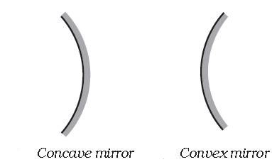
The reflecting surface of a spherical mirror may be curved inwards or outwards. A spherical mirror, who's reflecting surface is curved inwards, that is, faces towards the centre of the sphere, is called a concave mirror.
A spherical mirror, whose reflecting surface is curved outwards, is called a convex mirror. The surface of the spoon curved inwards can be approximated to a concave mirror and the surface of the spoon bulged outwards can be approximated to a convex mirror.
The centre of the reflecting surface of a spherical mirror is a point called the pole. It lies on the surface of the mirror. The pole is usually represented by the letter P.
The reflecting surface of a spherical mirror forms a part of a sphere. This sphere has a centre. This point is called the centre of curvature of the spherical mirror. It is represented by the letter C.
The radius of the sphere of which the reflecting surface of a spherical mirror forms a part, is called the radius of curvature of the mirror. It is represented by the letter R. When a straight line passing through the pole and the centre of curvature of a spherical mirror. This line is called the principal axis.
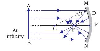
The light from the Sun is converged at a point, as a sharp, bright spot by the mirror. In fact, this spot of light is the image of the Sun on the sheet of paper. This point is the focus of the concave mirror. The heat produced due to the concentration of sunlight ignites the paper.
A number of rays parallel to the principal axis are falling on a concave mirror. Observe the reflected rays. They are all meeting/intersecting at a point on the principal axis of the mirror. This point is called the principal focus of the concave mirror.
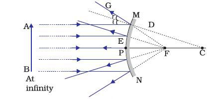
The reflected rays appear to come from a point on the principal axis. This point is called the principal focus of the convex mirror. The principal focus is represented by the letter F. The distance between the pole and the principal focus of a spherical mirror is called the focal length. It is represented by the letter f.
The reflecting surface of a spherical mirror is by-and-large spherical.
The surface, then, has a circular outline. The diameter of the reflecting surface of spherical mirror is called its aperture. For spherical mirrors of small apertures, the radius of curvature is found to be equal to twice the focal length. We put this as R = 2f .
A spherical mirror of small aperture, the principal focus F lies mid-way between the pole P and the centre of curvature C.
As we know the nature, position and relative size of the images formed by them.
The formation of images by spherical mirrors by drawing ray diagrams. Consider an extended object, of finite size, placed in front of a spherical mirror. Each small portion of the extended object acts like a point source. An infinite number of rays originate from each of these points. To construct the ray diagrams, in order to locate the image of an object, an arbitrarily large number of rays emanating from a point could be considered. However, it is more convenient to consider only two rays, for the sake of clarity of the ray diagram. These rays are so chosen that it is easy to know their directions after reflection from the mirror.
The intersections of at least two reflected rays give the position of image of the point object. Any two of the following rays can be considered for locating the image.
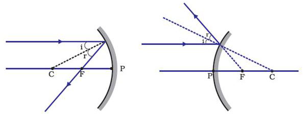
At the point of incidence, the incident ray is reflected in such a way that the angle of reflection equals the angle of incidence.
Uses of Concave Mirrors
Concave mirrors are commonly used in torches, search-lights and vehicles headlights to get powerful parallel beams of light. They are often used as shaving mirrors to see a larger image of the face. The dentists use concave mirrors to see large images of the teeth of patients.
Large concave mirrors are used to concentrate sunlight to produce heat in solar furnaces.
Uses of Convex mirrors
Convex mirrors are commonly used as rear-view (wing) mirrors in vehicles. These mirrors are fitted on the sides of the vehicle, enabling the driver to see traffic behind him/her to facilitate safe driving. Convex mirrors are preferred because they always give an erect, though diminished, image. Also, they have a wider field of view as they are curved outwards. Thus, convex mirrors enable the driver to view much larger area than would be possible with a plane mirror.
While dealing with the reflection of light by spherical mirrors, we shall follow a set of sign conventions called the New Cartesian Sign Convention.
The principal axis of the mirror is taken as the x-axis (X′X) of the coordinate system. The conventions are as follows -
These sign conventions are applied to obtain the mirror formula and solve related numerical problems.
In a spherical mirror, the distance of the object from its pole is called the object distance (u). The distance of the image from the pole of the mirror is called the image distance (v). The distance of the principal focus from the pole is called the focal length (f) . There is a relationship between these three quantities given by the mirror formula which is expressed as –
1/v + 1/u = 1/f
This formula is valid in all situations for all spherical mirrors for all positions of the object.
Magnification
Magnification produced by a spherical mirror gives the relative extent to which the image of an object is magnified with respect to the object size. It is expressed as the ratio of the height of the image to the height of the object. It is usually represented by the letter m. If h is the height of the object and h′ is the height of the image, then the magnification m produced by a spherical mirror is given by :
m = Height of the image(h')/Height of the image(h)
m = h'/h
The magnification m is also related to the object distance (u) and image distance (v). It can be expressed as:
Magnification (m) = h'/h = v/u
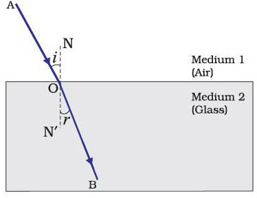
When a thick glass slab is placed over some printed matter, the letters appear raised when viewed through the glass slab. This phenomenon is known as refraction of light. There are various Examples in the world.
— The coin becomes visible again on pouring water into the bowl. The coin appears slightly raised above its actual position due to refraction of light.
Refraction is due to change in the speed of light as it enters from one transparent medium to another. Experiments show that refraction of light occurs according to certain laws. The following are the laws of refraction of light.
The refractive index can be linked to an important physical quantity, the relative speed of propagation of light in different media. It turns out that light propagates with different speeds in different media. Light travels fastest in vacuum with speed of 3x10⁸ms-1. In air, the speed of light is only marginally less, compared to that in vacuum. It reduces considerably in glass or water. The value of the refractive index for a given pair of media depends upon the speed of light in the two media.
n21 = Speed of light in medium 1/Speed of light in medium 2 = v1/v2
Absolute refractive index of some material media
|
Material medium |
Refractive index Value |
|
Air |
1.0003 |
|
Ice |
1.31 |
|
Water |
1.33 |
|
Alcohol |
1.36 |
|
Kerosene |
1.44 |
|
Fused quartz |
1.46 |
|
Turpentine oil |
1.47 |
|
Benzene |
1.50 |
|
Crown glass |
1.52 |
|
Canada Balsam |
1.53 |
|
Rock salt |
1.54 |
|
Carbon disulphide |
1.63 |
|
Dense flint glass |
1.65 |
|
Ruby |
1.71 |
|
Sapphire |
1.77 |
|
Diamond |
2.42 |
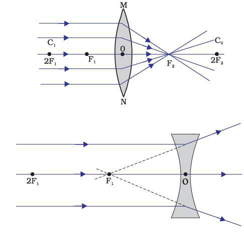
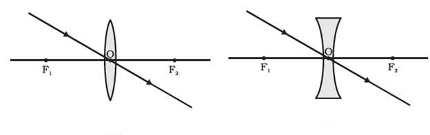
A transparent material bound by two surfaces, of which one or both surfaces are spherical, forms a lens. This means that a lens is bound by at least one spherical surface. In such lenses, the other surface would be plane. A lens may have two spherical surfaces, bulging outwards. Such a lens is called a double convex lens. It is simply called a convex lens. It is thicker at the middle as compared to the edges.
Hence convex lenses are also called converging lenses. Similarly, a double concave lens is bounded by two spherical surfaces, curved inwards. It is thicker at the edges than at the middle.
A lens, either a convex lens or a concave lens, has two spherical surfaces. Each of these surfaces forms a part of a sphere. The centers of these spheres are called centers of curvature of the lens.
Lenses form images by refracting light. The nature, position and relative size of the image formed by convex lens for various positions of the object.
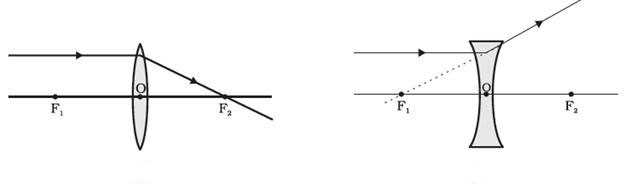
Ray diagrams will also help us to study the nature, position and relative size of the image formed by lenses. For drawing ray diagrams in lenses, alike of spherical mirrors, we consider any two of the following rays —
A ray of light from the object, parallel to the principal axis, after refraction from a convex lens, passes through the principal focus on the other side of the lens.
A ray of light passing through a principal focus, after refraction from a convex lens, will emerge parallel to the principal axis.
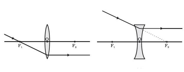
A ray of light passing through the optical centre of a lens will emerge without any deviation.
The rules for signs of distances, except that all measurements are taken from the optical centre of the lens. According to the convention, the focal length of a convex lens is positive and that of a concave lens is negative. You must take care to apply appropriate signs for the values of u, v, f, object height h and image height h′.
A formula for spherical mirrors, we also have formula for spherical lenses. This formula gives the relationship between object-distance (u), image-distance (v) and the focal length (f ). The lens formula is expressed as :
1/v – 1/u = 1/f
The lens formula given above is general and is valid in all situations for any spherical lens. Take proper care of the signs of different quantities, while putting numerical values for solving problems relating to lenses.
Magnification
The magnification produced by a lens, similar to that for spherical mirrors, is defined as the ratio of the height of the image and the height of the object. Magnification is represented by the letter m. If h is the height of the object and h′ is the height of the image given by a lens, then the magnification produced by the lens is given by,
m = Height of the image/Height of the object = h'/h
The power of a lens is defined as the reciprocal of its focal length. It is represented by the letter P. The power P of a lens of focal length f is given by
P = 1/f
The SI unit of power of a lens is ‘dioptre’. It is denoted by the letter D. If f is expressed in metres, then, power is expressed in dioptres. Thus, 1 dioptre is the power of a lens whose focal length is 1 metre. 1D = 1m-1.
You may note that the power of a convex lens is positive and that of a concave lens is negative.